
We finally achieved our milestone TiGL 3.1.
Together with our partners from Airbus Defense and Space and DLR Institute of System Architectures in Aeronautics, we implemented some major futures. The most notable features of TiGL 3.1 are:
- Full support of CPACS 3.1. In many cases, TiGL 3.1 can still load CPACS 3.0 files and will warn, if problems are expected.
- We backported support for trailing edge devices from TiGL 2. It is now possible to manipulate trailing edge devices with TiGL 3.1 using the TiGL Viewer, the API or the language bindings.
- Added support for generic fuselage walls. These can be used to model floors, landing gear bays, weapon bays and much more.
- Support for fuselage profiles with kinks.
- Added support for new symmetry flags
inheritandnone. The symmetry flaginheritcauses a geometric component to inherit the symmetry flag from its parent geometry. This was and still is the default behavior in TiGL. The new symmetry typenoneallows the addition of components to mirrored geometries without respecting the symmetry of the parent. - Numerical improvements of fuselage surfaces. This was done to improve the speed and robustness of boolean operations with the fuselage.
- Several smaller improvements and fixes.
The complete changelog can be seen at our TiGL 3.1.0 release page.
Conversion to CPACS 3.1
To update a CPACS 3.0 file to 3.1, use our cpacs2to3 tool as follows
cpacs2to3 -i mycpacs30.xml -o mycpacs31.xml -v 3.1
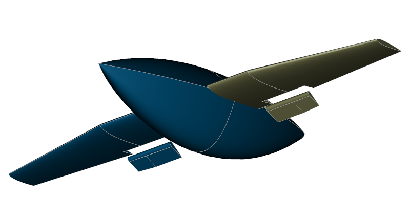
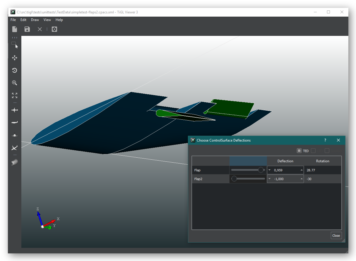
Trailing edge devices
TiGL 2 users already know the support for trailing and leading edge devides.
At this point, only trailing edge devides are supported yet. Allthough leading edge devices are very similar modeling-wise, we still need to perform some refactoring of the CPACS abstraction layer to reuse the same code for the different CPACS nodes.
In TiGL Viewer, the flaps can be moved using the sliders in the control surface dialog as depicted in the next image:
Fuselage walls
Together with Airbus Defense and Space and the DLR Institute of System Architectures in Aeronautics we developed the "generic walls" feature. This enables modeling a whole range of walls inside the fuselage. Particularly useful is the possibilty to trim walls with other walls. This way, many different geometries can be realized as e.g. compartments, floors, ducts, engine inlets and much more.
The following four images are screenshots from our unit tests, which aleady demonstrate the range of walls and compound walls for the different use cases:

These CPACS models (test_fuselage_walls_ex*.xml) can be downloaded here.
CPACS 3.3 preview: fuselage kinks
More unconventional and military aircraft often have sharp kinks on the fuselage. Until now, sharp kinks could not be explicitly modeled into fuselages though, making it very hard to achieve a fuselage that at least resemble the kinks a bit.

TiGL 3.1. already includes a CPACS 3.3 definition that enables the modeling of kinks. The principle is very simple: In addition to the points that are interpolated by a B-spline, another array kinks can be defined, which contains the indices of points that will interpolated with a kink.
A very simple example is the following:
<pointList>
    <x mapType="vector">0.0;0.0;0.0;0.0;0.0</x>
    <y mapType="vector">0.0;1.0;0.0;-1.0;0.0</y>
    <z mapType="vector">1.0;0.0;-1.0;0.0;1.0</z>
    <kinks mapType="vector">1;3</kinks>
</pointList>
Here, the point 1 (0, 1, 0) and point 3 (0, -1, 0) will contain a kinks, resulting in an eye-like shape of this profile.
Combining kinks
When multiple profiles are lofted into a surface or solid it is often desired that the kinks of the profiles are connected, i.e. such that the surface contains one kink that passes through the kinks of the profiles.
Still, this does not happen automatically. The reason is the following: the surface interpolation connects only those profile points that have the same curve parameter. If the kinks do no lie on the same curve parameter, e.g. if the profiles are different, multiple kinks in the surface can be the result, like in the following image.

Now, the surface containts three kinks on each side. Each kink is generated by one profile. This is clearly not what was intended. To fix this, CPACS 3.3 now allows to pin points to a specific curve parameter. All we have to do is to fix the points of the kinks to the same curve parameter by adding a parameterMap node to all profiles as follows:
<pointList>
    <x mapType="vector">...</x>
    <y mapType="vector">...</y>
    <z mapType="vector">...</z>
    <kinks mapType="vector">1;3</kinks>
    <parameterMap>
        <pointIndex mapType="vector">1;3</pointIndex>
        <paramOnCurve mapType="vector">0.25;0.75</paramOnCurve>
    </parameterMap>
</pointList>
This parameter map pins the first kink to curve parameter 0.25 and the other kink (point 3) to curve parameter 0.75. Now, the resulting surface looks as expected.
