
Parametric modeling of engine nacelles and pylons are now possible with TiGL 3.0.
Within the DLR internal project Victoria, parametric descriptions of both engine pylons and engine nacelles were added to the CPACS standard. Previously these airplane components could only be added as an external geometric component, that is by linking a CAD file in the CPACS file.
Engine nacelles
In CPACS, an engine nacelle consists of three components, a fan cowl, a center cowl and a core cowl.
- The fan cowl defines the outer geometry that is exposed to the external airflow. It is parametrized using a set of profile curves that are arranged at different angles and radii around the engine's symmetry axis. The profile curves are defined using two dimensional points and additional guide curves can be used to modify the surface generation. Optionally, a rotationally symmetric inner surface can be defined, as this is mandatory for the fan.
- The core cowl separates the bypass airflow from the internal combustion chamber. It is defined analogously to the fan cowl.
- The center cowl is the geometry of the shaft without the blades. It is defined using two-dimensional points that define a rotation surface around the engine's symmetry axis.
Engine pylons
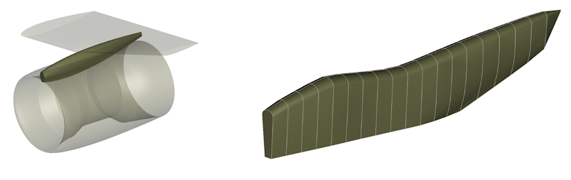
Pylons are modeled analogously to wings. They are defined using a curve network of profile and guide curves. These curves are defined as a set of two-dimensional points in the CPACS file.
Simple example CPACS files for both pylons and nacelles can be found in the test suite of TiGL on Github.