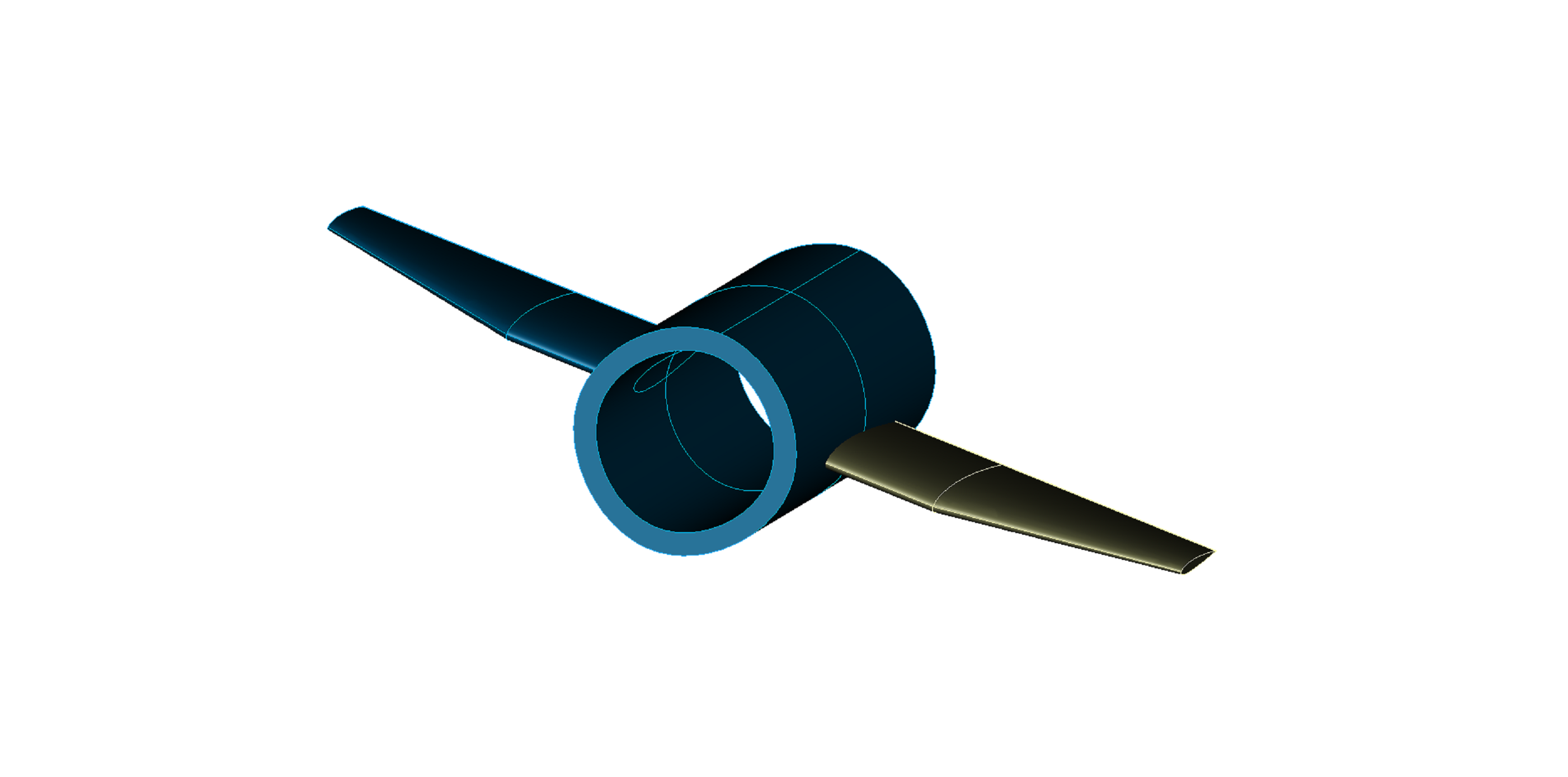
We are happy to announce TiGL’s new duct feature, that will be included in the coming release. It allows the user to create duct cutouts in wings and fuselages.
Based on a corresponding new CPACS development, TiGL was extended to support ducts and duct assemblies for aircraft configurations. It is to mention, that currently wings and fuselages are the only components that enable duct cutouts.
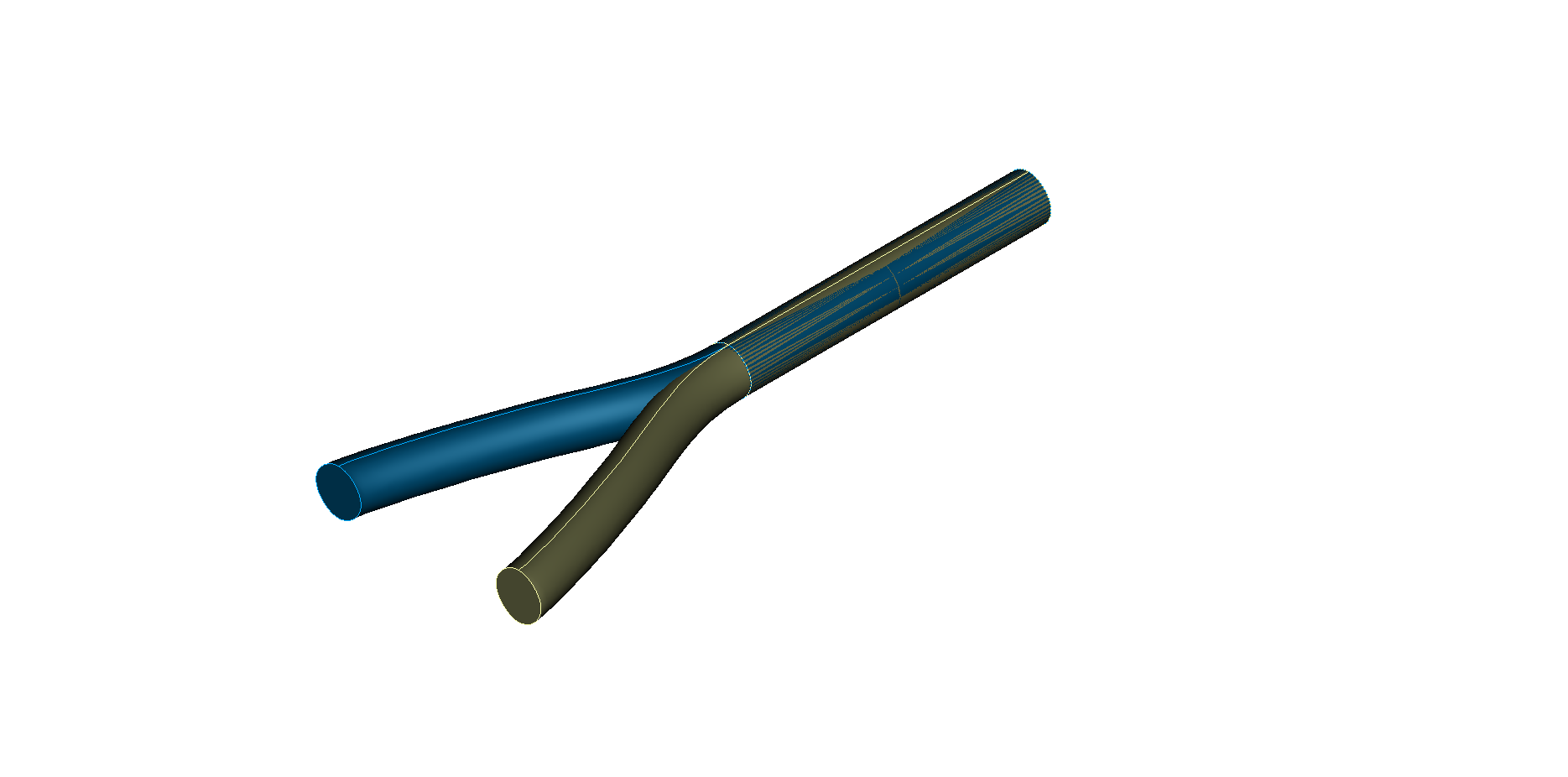
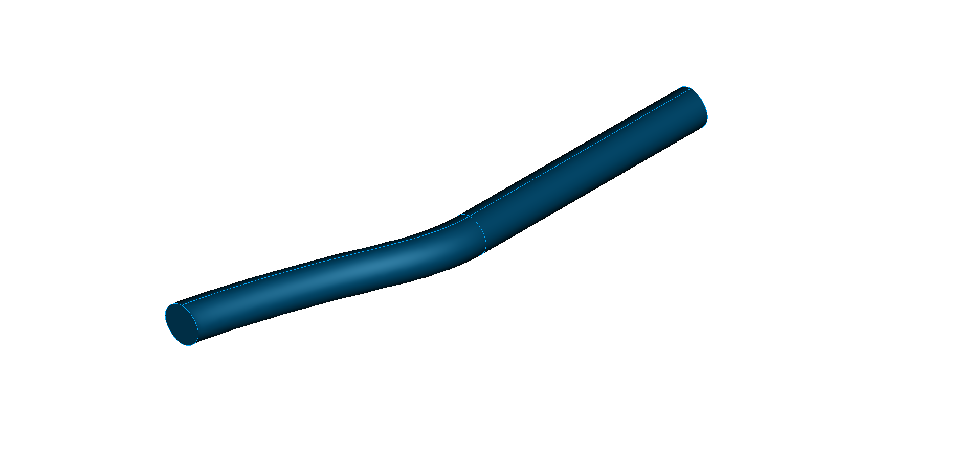
Duct geometry
As for the case of a fuselage, the geometry of a duct is modelled using a network of profile and guide curves.
Ducts are implemented in such a way, that TiGL always considers them as solids.
Basic modelling workflow
The related basic modelling workflow is as follows:
-
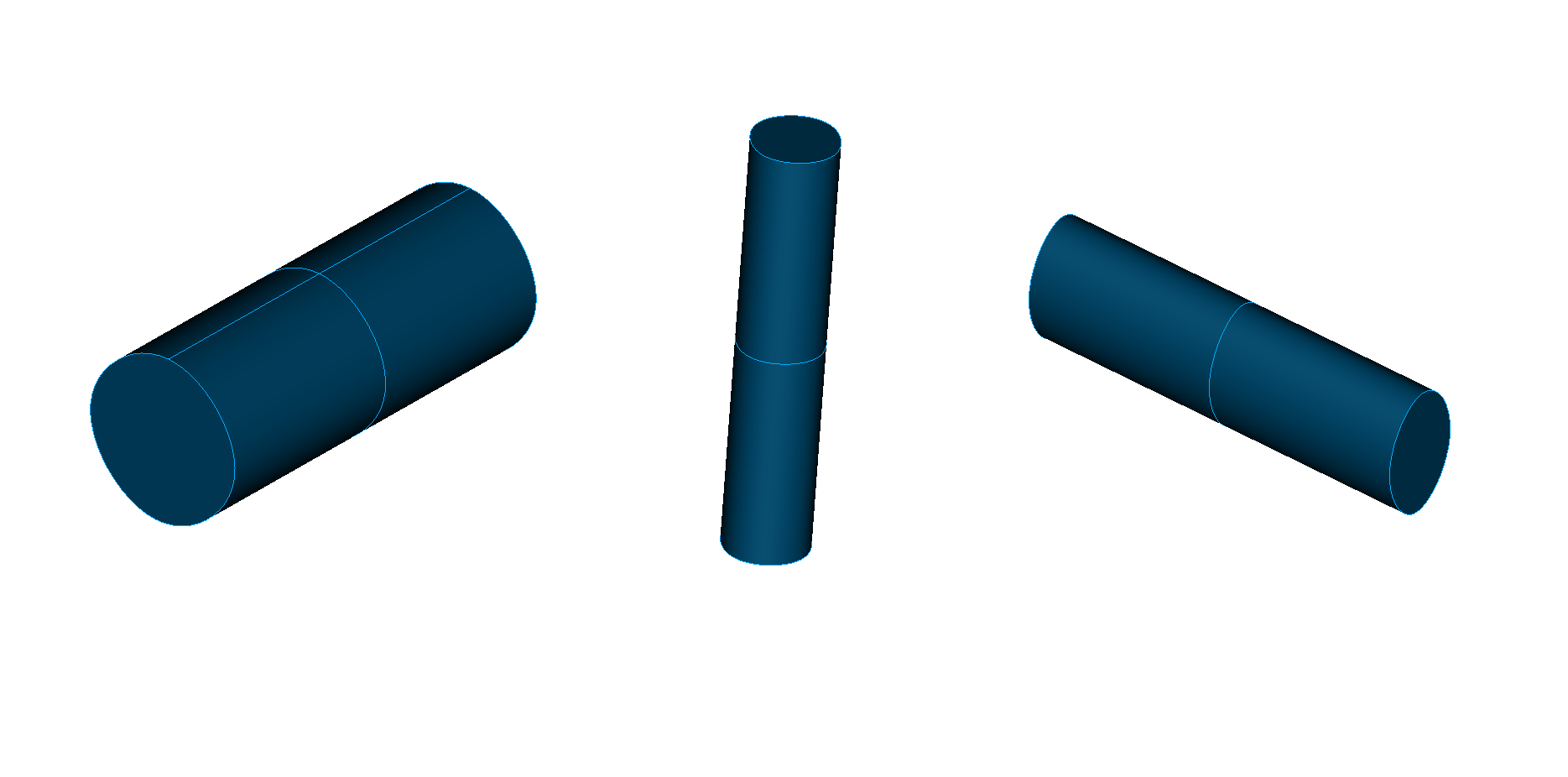
Define ducts.
-
Define duct assemblies. Each duct assembly references the ducts it is composed of.
-
Use the duct assemblies as a cutting tool to create cutouts of wings and fuselages via Boolean subtraction.
Exclusion lists
For a higher level of control, there is an option to define an exclusion list for each duct assembly. Such a list contains the particular wings and fuselages that should not be cut by the considered assembly.
<excludeObjectUIDs>
              <uID>Fuselage</uID>
</excludeObjectUIDs>
Symmetry flag
Furthermore, ducts come with a symmetry flag, allowing the user to save modelling time in the case of symmetric configurations.